LINK-US Co., Ltd.

Past Workpiece Examples

Bonding flexible printed circuit boards (FPC) for semiconductors

Bonding flexible printed circuit boards (FPC) for semiconductors

Power devices Plate x Wire
Workpiece example of bonding flexible printed circuit boards (FPC) for semiconductors

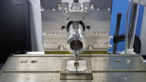
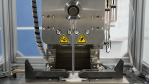
Photo 2. Bonding work(provided by Elephantech Inc.)

Flexible printed circuit boards are thin, flexible, maintain their electrical properties even when deformed, and are used as bonding cables to connect substrates and various electronic precision equipment, such as mobile terminals, PCs, cameras, and other digital equipment that require thin and light circuit boards.
The thin and flexible structure of flexible printed circuit boards can cause the adhesive layer on the bonding surface to come off and cause poor bonding when the adhesive layer and conductor foil are solder bonded over a thin film of insulation. This can cause defects like deformation when bonding with high temperatures such as in wire bonding.

For ultrasonic bonding using our complex vibration technology, the vibration trajectory is not folded back which makes it very efficient in eliminating oxide layers at bonding interfaces and promotes metal bonding through plastic flow.
Additionally, having no folded back vibration trajectories makes it is suitable for bonding fine parts as it allows for low-energy, non-intrusive bonding.
Bonded workpieces and result details

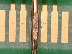
Photo 2. Photo after bonding (enlarged with a microscope)

The bonding workpiece was provided by Elephantech Inc.
The bonding tests were carried out using the following workpiece and test conditions for flexible printed circuit boards (FPC).

<Workpiece details>

Top workpiece part: single copper wire φ 0.135
Bottom workpiece part: FPC copper board (flash gold plated)

<Bonding result details>

Bonding time: 0.1 sec.
Amplitude: 80%
Static pressure: 80 N
Bond depth control: 50 µ m.
Energy: 2.5 J.

Having no folded back vibration trajectories allowed for low-energy, non-intrusive bonding for the workpieces used in this test as well.
Additionally, the horn tip (consumable) was bonded without breaking it even with its long and narrow dimensions as shown in Photo 1.
Tensile test results and bonding summary

Photo 3. Photo after tensile test (enlarged with a microscope)

A tensile test was performed after the above bonding test. The results of the tensile strength are as follows:

Bonding strength: Base metal fracture

In conclusion, bonding was successful without cuts in bond ends.
Due to the strength of the base metal being unmeasurable using a tensile test machine, we were able to obtain a bonding strength almost equal to the strength of the base metal as the base metal fracture was confirmed after removing it by hand.

Our horn tips can be designed to match your workpiece's geometry. Feel free to contact us by visiting the Contact Us page on our website.
Return to the list